3d model of a Machine Tools Warehouse MD001
Background
A few months ago, I decided that it was time to upgrade my Taig CNC mill to something larger. My target was to double the travel the working envelope of the Taig (12" X, 5.5" Y, 6" Z). The other constraint was I would need to be able to move the machine into my basement down a set of stairs. This rules out a Bridgeport or other "big iron".
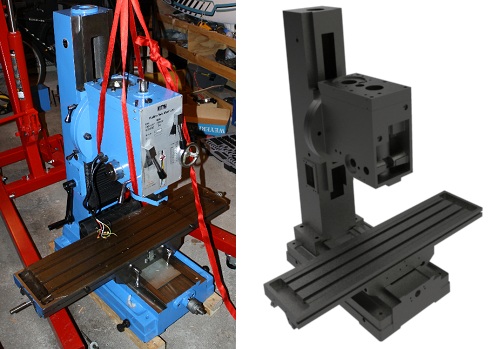
After some searching, I came across the Machine Tools Warehouse MD001 milling machine.
- Table Size: 39.5" x 9.375"
- X Travel: 30"
- Y Travel: 12"
- Z Travel: ~20"
- Gear head with 6 speeds (will not likely use this)
- ISO30 taper spindle - This was an option I added with the view to add a tool changer later
- Weight: 1000lb
This machine has the travel I am looking for with enough mass to use it. Since the column is the heaviest piece at 300lb, the machine can be moved into my basement with minimal fuss. This machine is also a clone of the Industrial Hobbies mill. Lots of these have been converted to CNC so there is a fair bit of information on the net. Since I am in Canada, the Machine Tools Warehouse was the best choice (and were cheaper!).
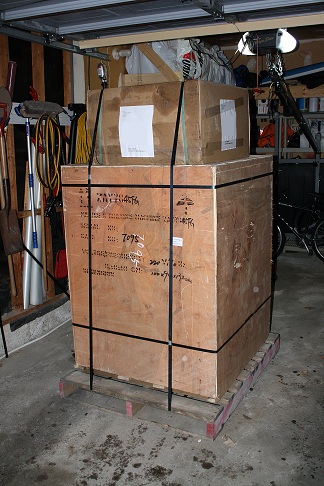
The Mill Arrives
A few months after placing the order, the mill was delivered to my house. Since I don't have a forklift or level loading dock, I paid extra for a lift-gate truck. Unloading from the truck was surprisingly painless with the mill in my garage in about 5 minutes. The slight uphill slope to my driveway posed no problem for the handtruck to negotiate.
The crate in my garage. The stand is the box strapped to the top of the crate.
Lets see what is inside!
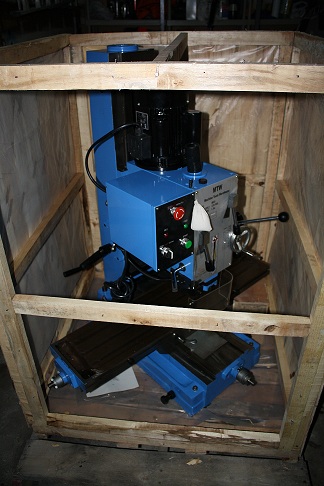
The mill was in great shape and there was no shipping damage. All of the bearing surfaces appeared to be ground (as advertised) and the movement was smooth on all three axis.
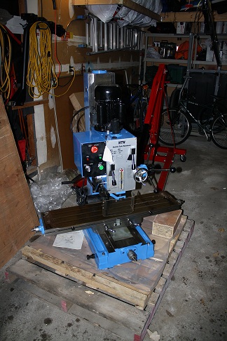
Disassembly
The first step was to disassemble the mill into pieces small enough to move down a flight of stairs. Here are the steps I used:
- Remove the electronics:
The electronics box on the side is easily removed by taking out the screws on the front and back first. Then the screws that hold the box to the mill may be removed. The motor and spindle limit switches should be disconnected at this time.
- Drain the oil from the head:
Since we will be tipping the head on its side in further steps, it should be drained of oil. The oil in my mill was an interesting colour and it was probably good to replace it anyway. There is a oil drain on the underside of the head which I found after disassembling the mill :)
- Remove the motor:
This step was surprisingly difficult. The trick is to get a couple of pry bars between the motor and the head and then lever the motor off. The motor shaft is a tight fit into the head and needs a bit of (gentle) force to get it apart.
- Lift the mill off the skid:
I used an engine hoist with 1" nylon webbing (4000lb strength) around the column and head to lift the mill. Care must be taken to insure that the center of gravity is below the lift point. I needed to move the mill off the skid to get the hoist close enough to remove the head and column. Once the mill is in the air, remove the skid, and lower the mill.
- Remove the head:
Place a sling around the head (four points minimum) and put some tension on the sling using the hoist. Remove the three bolts holding the head to the column slide and swing the head out of the way. I put some scrap wood over the table during this step just in case something went wrong. The head is heavy (>200lb) and top heavy.
- Remove the table:
I ran the table to one end of travel then removed the lead screw supports on the ends of the table. Second, I removed the gib and the leadscrew. Once these were out of the way it was fairly easy to slide the table off and move it out of the way. Note that you can only remove the table by sliding it off the end of travel. Even with the gib removed, you can't lift it off.
- Remove the saddle:
More or less the same steps as for the table. The only trick is the Y axis nut fits into a pocket in the saddle so the saddle must be lifted slightly while sliding it off the front of the mill.
- Remove the column:
I left the column slide on to give something to lift from. I ran it to the top of the column and ran the webbing around it. Once the webbing was tensioned, I found that the bolts holding the column to the base require a 12mm allan key. Make sure you have one before beginning this step, I didn't :) Other than the 12mm allan key, the column lifted right off the base though it did "stick" a bit. The secondary attachment method is bondo and paint. You may have some shims between the column and the base to tram the mill. I didn't, but I don't know if that is a good thing or not. That will have to wait until it is re-assembled.
Once the mill was disassembled, it was not too hard to move into the basement using a dolly. The column was the worst piece to move as it is the heaviest and is also bulky.
3d Model
Now that the mill was in pieces in my basement, I decided that it was a good time to create a model of the main castings. Since I plan to convert to CNC, this should make things much easier. With the model I will be able to design the servo supports, enclosure, and other features without trial and error.
I recently purchased Alibre Design Expert and will be using this for the modeling. I have to say that Alibre is a great tool for the price and is a major step up from AutoCad 2000 that I was using before. I highly recommend this software and the current price of $97 for the base version is an excellent deal.
Now the model:
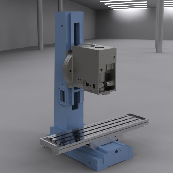
The base, saddle, table, column, column slide, head, and head top are all modeled as separate entities. The Alibre assembly has the constraints defined that allow the mill table and head to be moved around into any location. I attempted to replicate all of the dimensions and hole locations as closely as possible to my set of castings. It is very likely that your castings will have slightly different hole locations especially. Do not use the model without checking against your own machine!
Enjoy!