Click for actual .dxf file
In my quest to create new and interesting uses for my CNC mill, I found a link to Darali Drives. The link came courtesy of a thread on CNCzone and inspired me to devote a few weekends to creating a hypocycloidal reduction drive (also know as a cycloidal speed reducer). The main reason I was draw to this approach to speed reduction was the apparent machinablity of the parts with only a 3 axis mill. The profile of the cams allows the use of relatively large (0.125" in my case) endmills and does not require the internal shaping a gear does. The other attributes of the drive are also attractive, with zero backlash and high shock loading being some of the key features. I don't expect to get zero backlash on my first attempt :)
See the Hypocycloid at Wikipedia for details of what a hypocyloid is. If you have ever played with a Spirograph, you have seen a hypocycloid. Now the problem with the hypocycloidal form used in this drive is that it can't be drawn using simple geometry in a CAD program. I did try in Autocad and got quite close, but the resulting form had many sticky spots and was very difficult to modify. As a result, I decided to create a script to generate the profile automatically.
Some research and another check on the thread at CNCzone brought up a post by aystarik. The linked pdf was most informative as it contained the mathematical formula describing the hypocycloid cam. The Russian was translated using Google to understand the terms. The reason the formula is more complex than the Wikipedia entry is to allow the offset cause by the outer rollers having a finite diameter. See the attached script for the math.
Further research led to the a paper by Anamaria Dascalescu on how to determine the optimal relief location on the cam. The math from this paper has been integrated into v0.2 of the script. This allows the cam profile to be set back when the pressure angle is greater than a set amount (50 degrees is recommended).
I have created a new version of the script that has many bug fixes and is much easier to use as there is graphical feedback. A alpha version is here for evaluation but I am not ready to release the code as it needs a bit more work. The other difference is that it does not generate a DXF file but instead a text file with a list of x-y coordinates. These coordinates can be imported into your CAD package of choice as a series of spine control points. This tends to make modern CAD packages happier.
To create a machinable profile, I needed to create a .dxf of the above formula. Since I am not familiar with AutoLisp I decided to use Python as I have a passing familiarity with it. Python is also cross platform and the script (should) be able to be used on any OS and the .dxf files used in any CAD/CAM program. After finding the .dxf library for Python, it was easy to generate the correct profile. Note that the script was written for Python 2.6 and I have had reports of it not working on 3.0. If you want to create your own profile, get the script here. It is fairly self explanatory and generates output files like this:
Click for actual .dxf file
All parts were machined from Delrin on my Taig mill. A 0.250" cutter was used for roughing and a 0.125" cutter was used to finish the cam profiles. The cams were cut 0.001" undersize to stay away from a press fit, but I believe that I could get away with cutting them on size in the next version. There is a very small amount of backlash in the output stage due to this (I believe). I have not measured it, but it seems to be less than a degree by eye.
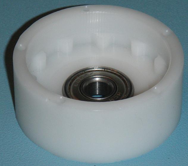
The housing:
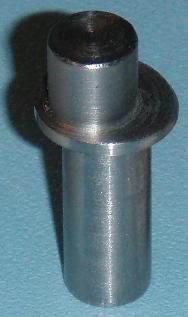
The eccentric shaft:
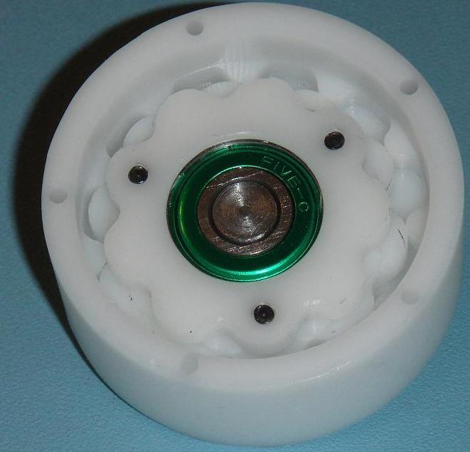
Top view of the cam showing the 10 lobe side:
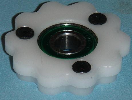
Bottom view of the cam showing the 9 lobe side:

Output drive:
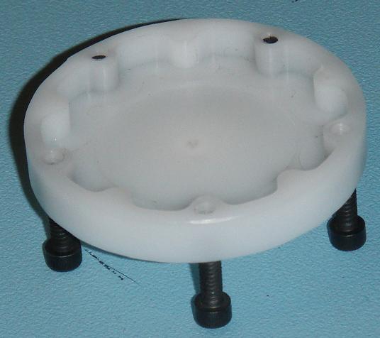
Cam in the housing: